What Data Center Redundancy Really Means (Beyond Basic Definitions)
In common parlance, redundancy is often conflated with "having a spare." In a mission-critical environment, the distinction is much sharper. Redundancy is the intentional duplication of critical components to increase system availability, whereas fault tolerance is the ability of a system to continue operating without interruption during a failure.
A redundant system might experience a momentary "hiccup" during a failover; a fault-tolerant system is designed so that the end-user never knows a failure occurred. For the enterprise, the primary goal of redundancy is the elimination of Single Points of Failure (SPOFs). An SPOF is any individual component a circuit breaker, a cooling pump, a network switch that, upon failing, brings down the entire service.
Designing for redundancy requires "failure thinking." It is not enough to have two of everything; those two components must be physically and logically isolated so that a fire, surge, or leak affecting one does not compromise the other.
Power Redundancy Models: N, N+1, 2N, and 2N+1
Power is the lifeblood of the data center, and its redundancy model dictates the facility’s fundamental reliability tier.
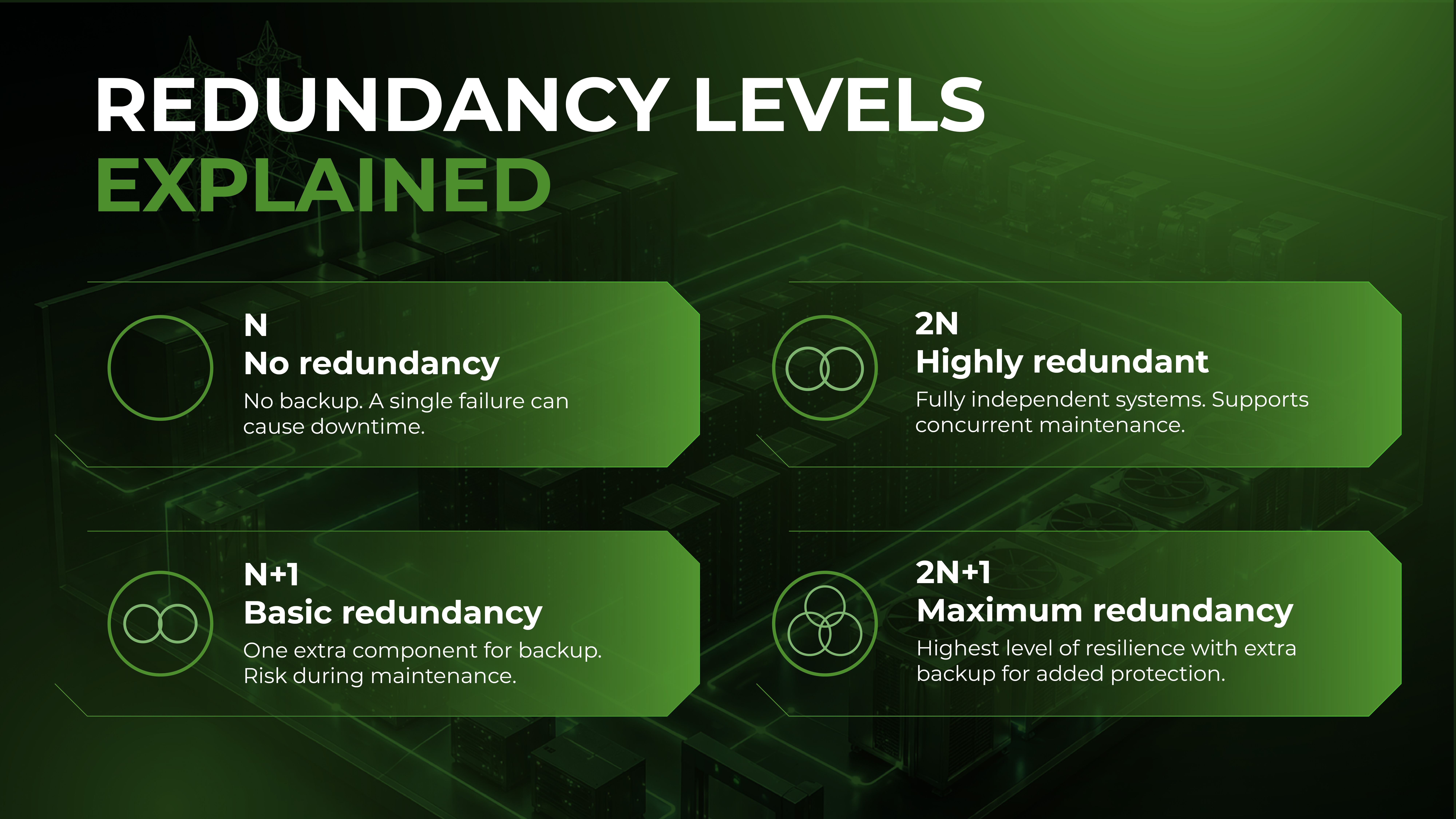
The N Model (Base Requirement)
"N" represents the capacity required to power the facility at full load. In an N architecture, there is zero redundancy. If a UPS (Uninterruptible Power Supply) fails or a generator refuses to start during a utility outage, the load drops. This is unsuitable for enterprise workloads.
The N+1 Model (Parallel Redundancy)
In an N+1 system, there is one extra unit for every 'N' units required. For example, if a data hall requires four UPS units to run, the provider installs five.
-
Failure Scenario: If one UPS fails, the remaining units absorb the load.
-
The Catch: N+1 protects against component failure but often fails during maintenance. If you take a unit offline for service, you are back to 'N' leaving you with zero protection until the service is complete.
The 2N Model (System Redundancy)
2N architecture provides two independent, mirrored power systems (an A side and a B side). Each side is capable of supporting the entire load independently.
-
Failure Scenario: A total failure of the A-side switchgear or UPS string results in an immediate, seamless transition to the B-side.
-
Enterprise Standard: This is the baseline for Tier III Data Center standards. It allows for "Concurrent Maintainability," meaning any part of the power chain can be shut down for maintenance without impacting the servers, provided the equipment is dual-corded.
The 2N+1 Model
This is the gold standard, offering two complete 2N systems, each with its own N+1 internal redundancy. It provides the highest level of resilience, ensuring that even if a component fails while the other side of the system is down for maintenance, the load remains protected.
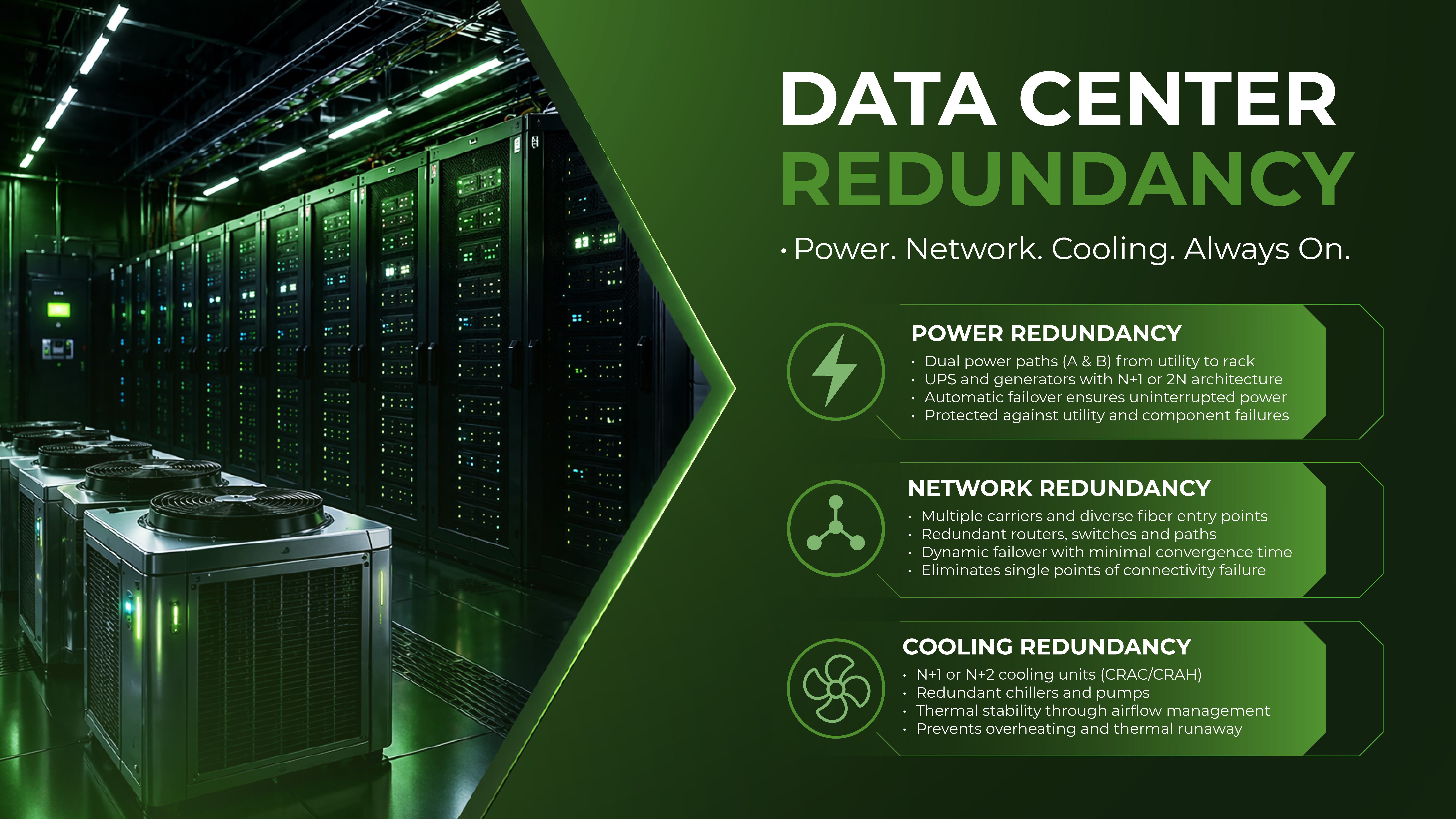
Network Redundancy: Ensuring Continuous Connectivity
A data center with 100% power uptime is useless if it is cut off from the internet. Network redundancy is about path diversity and carrier independence.
Carrier Diversity and the Meet-Me-Room (MMR)
True redundancy requires "Carrier Neutrality." This ensures the facility is connected to multiple independent telecommunications providers. If one carrier experiences a fiber cut or a BGP routing error, traffic can be instantly re-routed through another.
Physical Path Diversity
Architects must look at the "last mile" of fiber. Are the different carriers entering the building through the same conduit? If so, a single construction accident outside the building can take out all carriers simultaneously. A redundant facility must have diverse entry points ideally on opposite sides of the building leading to independent Meet-Me-Rooms.
Multi-Path Routing and Failover
At the logical layer, redundancy is managed through protocols like BGP (Border Gateway Protocol). In an enterprise-grade setup, network hardware (routers and switches) is also redundant (VRRP/HSRP), ensuring that the failure of a single line card or supervisor module does not result in a packet loss.
Cooling Redundancy and Thermal Risk Management
Cooling is the most frequently overlooked element of Data Center Redundancy, yet it is arguably the most volatile. If power fails, a UPS kicks in instantly. If cooling fails, you enter a state of "Thermal Runaway."
Why Cooling Redundancy is Critical
Modern high-density racks can generate immense heat. If the CRAC (Computer Room Air Conditioning) or CRAH (Computer Room Air Handler) units fail, the ambient temperature in a hot aisle can rise to damaging levels in less than five minutes. This can lead to automatic hardware thermal shutdowns or, worse, permanent silicon degradation.
N+1 in Cooling Systems
In a redundant cooling environment, the facility maintains extra CRAC units and redundant chilled water pumps. If a pump motor seizes, a secondary pump must automatically engage.
-
Thermal Stability: Beyond just "extra units," redundancy includes the ability to maintain static pressure and airflow patterns.
-
The Reservoir Effect: Advanced facilities use thermal storage tanks large reservoirs of chilled water that can continue to cool the data hall for several minutes even if the chillers fail to restart immediately after a power transition.
Conclusion
Data Center Redundancy is not an "add-on" feature it is the strategic foundation of business continuity. For the enterprise, the cost of redundant infrastructure is an insurance premium against the catastrophic costs of an outage.
A holistic approach to redundancy, covering power, network, and cooling, ensures that the infrastructure can withstand the inevitable reality of hardware failure and human error. When evaluating a partner, look beyond the labels. Reliability is not a static state; it is an engineered outcome of rigorous design and operational discipline.
At Silvernox, we prioritize engineered reliability. Our facilities are designed with the redundancy and concurrent maintainability that enterprise-scale operations demand. By aligning our Data Center Infrastructure with the highest industry standards, we provide our clients with the stability they need to scale with confidence, knowing their mission-critical workloads are protected by a redundant, resilient foundation.
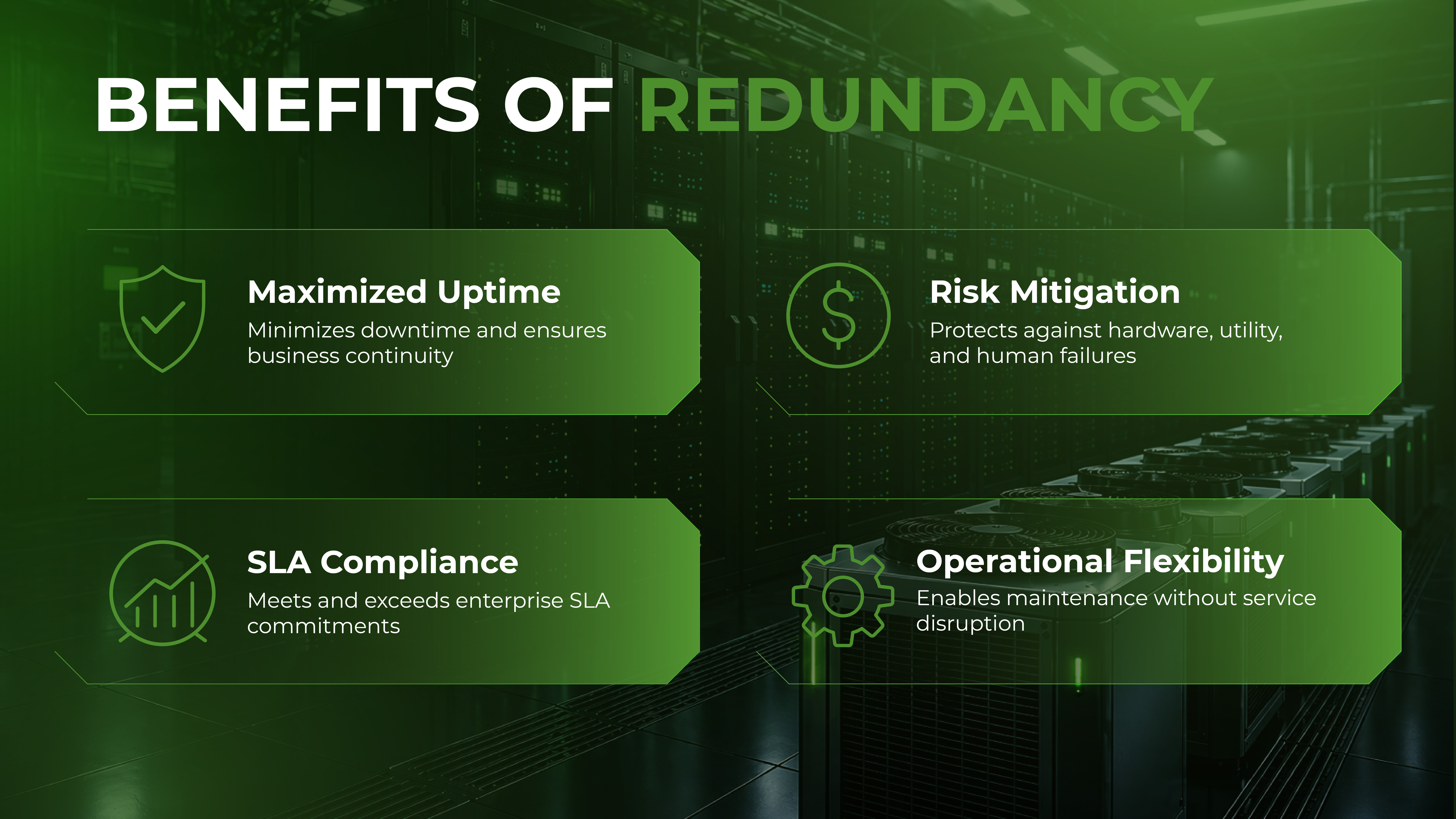
How Redundancy Directly Impacts Uptime and SLA Commitments
An SLA (Service Level Agreement) is a financial contract, but redundancy is the engineering reality that fulfills it. There is a massive operational gulf between "three nines" (99.9%) and "four nines" (99.99%).
-
99.9% Uptime: Allows for nearly 9 hours of downtime per year. This is typically achievable with N+1 power and basic cooling.
-
99.99% Uptime: Allows for only 52 minutes of downtime per year. This level of reliability is virtually impossible without a 2N power architecture and concurrent maintainability.
When redundancy is weak, failures tend to cascade. A minor power fluctuation might cause a cooling controller to reboot; if that controller isn't redundant, the chillers may stay off long enough for the servers to overheat and shut down. Redundancy is about breaking these "failure chains."
Mapping Redundancy to Tier III Data Center Standards
The Uptime Institute’s Tier Classification System is the industry benchmark for evaluating redundancy. For most enterprise applications, Tier III is the requirement.
Concurrent Maintainability
The defining characteristic of a Tier III facility is "Concurrent Maintainability." This means that every single component required to support the IT load including the power path, the cooling path, and the engines can be removed from service for planned maintenance without an outage.
In a Tier III environment, there are no "maintenance windows" that require the customer to shut down. If a provider tells you they are Tier III but requires a window to "service the main switchgear," they are likely operating at a Tier II level in practice.
What Enterprise Buyers Often Miss When Evaluating Redundancy
Evaluation often stops at the brochure. To truly understand a provider's reliability, decision-makers must look at the operational nuances.
-
Shared vs. Dedicated Redundancy: Some providers offer N+1 redundancy across the whole building, but if three customers in different halls experience failures simultaneously, the "extra" capacity is exhausted.
-
The "A+B" Cord Reality: Many enterprises pay for 2N power but have "single-corded" legacy hardware. Without a Static Transfer Switch (STS) at the rack level, that equipment is only as redundant as an N system.
-
Human Factors: Redundancy is often bypassed by human error. Does the provider have rigorous MOPs (Methods of Procedure) for switching between power paths?
-
Network Convergence Times: A redundant network path is useless if it takes two minutes for the routing tables to converge and restore connectivity. Enterprises should ask about historical failover performance.
Practical Redundancy Evaluation Checklist
When touring a facility or reviewing a Data Center Services proposal, use this checklist to validate redundancy claims:
Power Architecture
-
Is the power delivered via two independent paths (A and B) from the utility to the rack?
-
Are the UPS systems 2N or N+1?
-
Is there enough fuel on-site for at least 24–48 hours of generator runtime at full load?
Cooling and Environment
-
Is there N+1 or N+2 redundancy on CRAC/CRAH units in every data hall?
-
Is the cooling system connected to backup power (UPS or quick-start generators)?
-
Are there sensors at the top, middle, and bottom of the racks to monitor thermal gradients?
Network and Connectivity
-
Are there at least two physically diverse fiber entry points into the building?
-
Does the provider have a carrier-neutral Meet-Me-Room with 10+ providers?
-
Is the internal network backbone built on a redundant leaf-spine architecture?